Monoflo Heating System Diagram
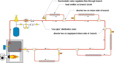
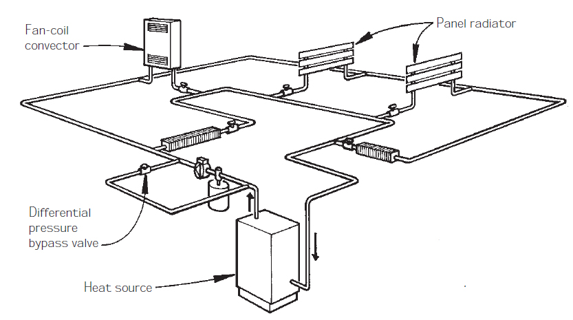
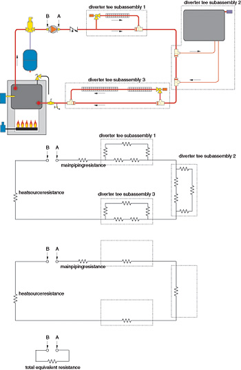
Monoflo heating system diagram. A circuitry diagram is a streamlined basic photo representation of an electrical circuit. Size the circulator based on total flow and overall system pressure drop. Create a map of the central heating system you want to install.
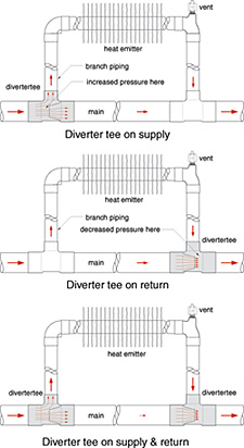
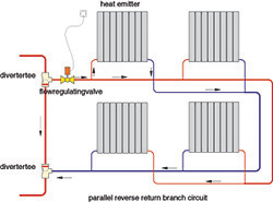
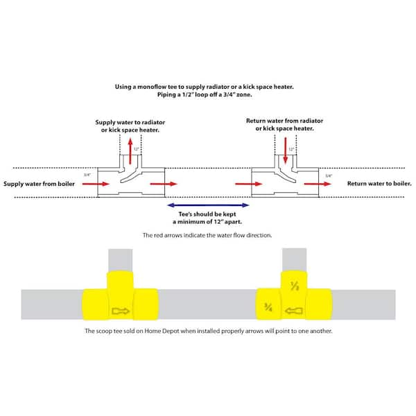
First tee a standard tee goes to the up-feed radiator. Do these special tees tell the water where to go. It is also important that the PLC be correctly wired into the panel.
Additionally if not installed properly flow problems will occur in radiators andor baseboards. Steps Research the equipment you want to use to install central heating in your home. Myson towel warmers and radiators are ideally suited for installation on a CLOSED system.
3 zone system with taco zone valves. Third tee a Monoflo comes from the up-feed radiator. By memory I can say that the main basement loop supply the monoflo Ts is hot till right before the last T that brings the largest loop back into the system right before the circulator On the boiler side of the T it stays cold for most of the boiler cycle.
The diverter tee system made installing hot water heating systems in new homes less labor intensive. If you remove it you would need to do one of two things. Second tee a Monoflo goes to the down-feed radiator.
See how to use 1. Customer complaining of temperature swings thru out the house also complaining some radiators not heating. It is really important if you have a monoflow system to consult a.
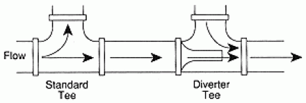
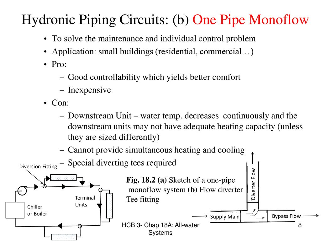
The Monoflo or Venturi tee came later after the invention of wet rotor circulators. Failure to observe this requirement may cause premature machine failure and could invalidate the warranty of the machine.
During the 1930s the Bell Gossett Company introduced their Monoflo tee the name is a trademark.
Heating 2nd floor monoflo venturi loop added - YouTube. These units are not recommended to. Use the approximate flow rate through the radiator and flow setter valve setting to read off the pressure drop. It went on to play a big part in American house heating during the years before World War II. Fourth tee a Monoflo comes from the down-feed radiator. During the 1930s the Bell Gossett Company introduced their Monoflo tee the name is a trademark. Information for each image - you can also click on images above to see this text. Zone 1 I found the wire for the end switch broken off the valve. If you dont do this the added restriction to flow in.
It is really important if you have a monoflow system to consult a. It is but the O-S preceded the Monoflo by many years. Second tee a Monoflo goes to the down-feed radiator. Lay the pipes from the radiators and faucets to. All zones are 1 split returns with 1-12 mains. These boilers have never operated above the. Use the approximate flow rate through the radiator and flow setter valve setting to read off the pressure drop.















Post a Comment for "Monoflo Heating System Diagram"